Arduino and other electronics projects info
First replies only links about charging projects

Feb 21, 2018 This is an electrostatic polarity detector with increased sensitivity. This device makes it possible to investigate the polarity of the high voltage. RED LED = Positive, BLUE LED = Negative, Both LED = Alternating Voltage On the HVDC line, only one LED will be on. How to make an Electrostatic Polarity Detector : - How to make an Electrostatic Polarity Detector(Electric Field Detector) https://www.youtube.com/watch?v=WptwVzK7cK0 > Jun 7, 2017 This is a simple Electrostatic Polarity Detector(Electric Field Detector) made of FDS8958A Chip. This chip(FDS8958A) contains N- and P- Channel Enhancement mode power field effect transistors. Old Version : Using 9V battery. New Version : Using 3V battery. The circuit diagram appears on the video. 07:13 ##### IRF 7317 is replacement part for FDS8958A - Thomas Kim 2017 [](https://lemmy.staphup.nl/pictrs/image/6acb077f-6f16-4469-8632-5198159d38a1.png) See improved schematic by Thomas Kim in 2018 https://lemmy.staphup.nl/comment/66129
Apr 3, 2012 For more from the AT&T Archives, visit http://techchannel.att.com/archives On an elementary conceptual level, this film reflects the multifaceted scientific hyperthinking that was typical of a Bell Labs approach. Host Dr. J.N. Shive's presence as a lecturer is excellent - it's understandable by a layperson even when he branches into equations, because he uses copious amounts of real-world examples to bolster the material. Shive's role at Bell Labs was more than just a great lecturer: he worked on early transistor technology, inventing the phototransistor in 1950, and the machine he uses in the film is his invention, now called the Shive Wave Machine in college classrooms. Dr. J.N. Shive of Bell Labs demonstrates and discusses the following aspects of wave behavior: Reflection of waves from free and clamped ends Superposition Standing waves and resonance Energy loss by impedance mismatching Reduction of energy loss by quarter-wave and tapered-section transformers Original audience: college students Produced at Bell Labs Footage courtesy of AT&T Archives and History Center, Warren, NJ

The original remote was missing, so I thought replacing the remote and receiver would be a nice challenge. Parts used: - An old 2 channel 40Mhz remote and receiver "Graupner b4 ssm 40b". - This ESC "40A Brushed Esc Electronic Speed Controller Voor Wpl C24 C34 Mn D90 MN99S MN86S" https://aliexpress.com/item/1005005133523842.html for converting PWM into a DC power supply for the already mounted DC motor. - A servo "MG90D Digital servo" to replace the original limit-switched-motor, for steering. (The "SG90 tower pro" with plastic gears didn't last) - Some 3d printed parts for steering. The original remote had - 1 channel (off/on) for the back connector (to attach a trailer) - 1 channel (off/left/right) for steering left/right - 1 channel (off/fw1/fw2/bk) for driving So i lose the option to control the back-connector, but i gain variable speed and steering control. [](https://lemmy.staphup.nl/pictrs/image/f28f1951-6915-422b-95d0-88fe5db89cf1.jpeg)
> Jan 2, 2020 > > hello guys!! > this is my first video in this video i am going to show you how to change output voltage of laptop power adapter ll it can give 5 volts to 35 volts output remove two feedback resistors in that place connect potential meter, you can find feedback resistors near the ic M101AC don't forget to change the output capacitors > THANK YOU!!!
part 1 https://www.youtube.com/watch?v=Su7VNLW8jWU part 2 https://www.youtube.com/watch?v=pMZoyhXmbr4 part 3 https://www.youtube.com/watch?v=9CpsH4miXKk part 4 https://www.youtube.com/watch?v=3Ie56eApfZU part 5 https://www.youtube.com/watch?v=smSFZksTrEA
To communicate you need: - Smartphone (BT) running "meshtastic app" - ↕ (BT) - IOT device (BT + LoRa) running "meshtastic firmware" - ↕ (LoRa) - IOT device (BT/WIFI+ LoRa) running "meshtastic firmware" - ↕ (BT) - Smartphone (BT) running "meshtastic app" Maps for finding such nodes: - one maintained by user: https://canvis.app/meshtastic-map - and an unofficial: https://map.technicallyrural.com/

i found this lightbox without keyboard at the second hand store. i thought i'd see what i could do. There's hardly any info on the Cresta AS-0216. The websites i found, looking like the same (or similar) device; - a Chilong "Ad-Pro AS-0216" https://www.amazon.com/AD-PRO-AS-0216-PROGRAMMABLE-LED-SIGN/dp/B00UDNDG6O - a Brandless AS-0216 https://www.elektroda.pl/rtvforum/topic1584838.html - This blog https://www.circuitsonline.net/forum/view/30396/1#highlight=cresta in search for AS-0216 material refers to http://www.kingpul.com.tw/ but that domain is no longer active. - "Kingpul" brand website can only be seen via the internet-archive; https://web.archive.org/web/20051214082253/http://www.kingpul.com.tw:80/rh216r.htm lists the type "RH-216R" which seems comparable. But no manual is downloadable - "Sigma ASC 333" is mentioned here https://www.hetlab.tk/artikelen/lichtkrant-protocol and states it is similar to the "Cresta RH-0214CR". This one has software for windows 95 available, and i could download the manual (via https://web.archive.org/web/20160904131325/http://anseyang.myweb.hinet.net/214CR.htm ) - https://elektrotanya.com/sigma_asc_333,as226_fenyujsag_software.zip/download.html It refers to this Kingpul site as well (only still internet archive) https://web.archive.org/web/20160904131325/http://anseyang.myweb.hinet.net/214CR.htm - Someone tried some things on an AS-0216 http://www.nerdkits.com/forum/thread/1256/ - "HiTech AS-0216" is also one of it's names; https://forum.arduino.cc/t/controlling-a-old-school-led-message-sign-hitech-as-0216-with-a-uno/367646 There's a blog about a repair of a Cresta-0216; - https://www.markgrob.nl/2021/04/cresta-as-0216-repair/comment-page-1/ But that device has a different print than mine. My device looks like this (pictures can be enlarged by clicking): - [](https://lemmy.staphup.nl/pictrs/image/8fbebdad-671f-44cf-8865-341fd2cde262.jpeg) - [](https://lemmy.staphup.nl/pictrs/image/bd078901-0707-45ac-a821-45019e124748.jpeg) - [](https://lemmy.staphup.nl/pictrs/image/521411c0-02fe-4bfa-865e-25f725f65070.jpeg) - [](https://lemmy.staphup.nl/pictrs/image/2b79769f-ff1b-4799-9cf2-cd00bccba25f.jpeg) - [](https://lemmy.staphup.nl/pictrs/image/c2ac5da4-f8a8-41b7-af83-3160ed138294.jpeg) i'll be posting some update if i have them
I've got a few damaged hoverboards. They're not very good quality. Some work others go into error-state after a while. To be able to do some fault finding i thought to try to readout what these sensorboards provide. This is the exact model i have  **Sensorboard gyroscope taotao 684270 2016-04-20** (where i found the pics: https://www.voltes.eu/products/hoverboard-sensorboard-gyroscope-taotao) i use the Arduino mega 2560, because it has multiple UART pins. ### Baud rate I first needed to know the baud rate. For that i found some online arduino code measuring the shorted pulse duration, and based on that determine the baud rate. Seems the board is communicating at 57600 baud. ### which UART mode To try to find out what UART mode is used, i created a program which determines the high/low durations of the data pin, and print it as a bitstream, hoping to be able to determine the mode. But i couldn't make sense of it(in hindsight, i can understand it, but i'm too much of a rookie). So i just tried the few available modes. None of the 5 to 8 databits modes produced anything useful. ### 9 bit data Turns out the standard Arduino 8 bit UART modes don't work. i needed to try the 9 bit UART mode. For that i used an external library mentioned on this site: https://forum.arduino.cc/t/9-bit-software-hardware-serial/590266/8 Because this library sets an interrupt routine, i renamed the HardwareSerial9bit0.cpp file to HardwareSerial9bit0.cpp.txt so that in my sketch it didn't collide with the Arduino IDE's **Serial** which i used for debug printing to the Arduino console. The mode which worked for **Serial91** is SERIAL_9O2 (9 databits, Odd parity, 2 stopbits ) ### Finding a frame To find the start of a frame, i decided to look for a 0, then 2 times a non-0, and a 0 after the frame. For storing the UART data in a buffer, i used the CircularBuffer library by AgileWare v1.3.3 https://github.com/rlogiacco/CircularBuffer . I set it to store 512 integers. When Arduino finished 1 cycle, there are between 10 and 60 integers read into the buffer. But when i enable printing of packets to Serial, then it increases to about 70 - 80 per cycle which are available. When the cyclical buffer contains more then 10 integers, i test if it contains a valid frame, if not, i remove the head, and test again. **Update:** I changed the frame detection because an actual 0 angle would not be possible. So now it tests for #0 to be 0, #5 to be 0x5 or 0xA, #10 to be 0. Also, i now realize that UART overflows at 64 characters.. i.e. the code must be improved to be faster. **/update** ### Data obtained The data packets are formatted as ``` * 000,102,002,102,002,01A,0B8,0B8,000,000,000, * AA BB AA BB CC DD DD EE EE FF * 000 = Start of frame * AA BB = LSB,MSB forward backward angle * CC = Status bits ( 0xA unpressed, 0x5 pressed, 0x20 Error/was upside down ) * DD = 9 bit unsigned 0..185..368 intertia left/right rotation * EE = 9 bit signed -255.. +255 intertia forward/backward rotation * FF = Start of next frame ``` ### Data issues The doubling of the data in a single frame enables some error checking. I observed the next issue ``` AA BB AA BB CC DD DD EE EE | 'AABB as dec nr' || Bad Angle reading is dodgy.. Bits are flipping on.offf V V V V 63 | 1E1 | 63 | 1E1 | 5 | B8 | B8 | 0 | 0 | -15773 || 63 | 1F1 | 63 | 1F1 | 5 | B8 | B8 | 0 | 0 | -7581 || BAD 73 | 1E1 | 73 | 1E1 | 5 | B8 | B8 | 0 | 0 | -15757 || BAD 63 | 1E1 | 63 | 1E1 | 5 | B8 | B8 | 0 | 0 | -15773 || 63 | 1E1 | 63 | 1E1 | 5 | B8 | B8 | 0 | 0 | -15773 || 73 | 1F1 | 73 | 1F1 | 5 | B7 | B7 | 0 | 0 | -7565 || BAD 63 | 1E1 | 63 | 1E1 | 5 | B8 | B8 | 0 | 0 | -15773 || BAD 73 | 1F1 | 73 | 1F1 | 5 | B8 | B8 | 0 | 0 | -7565 || BAD 63 | 1E1 | 63 | 1E1 | 5 | B8 | B8 | 0 | 0 | -15773 || BAD 72 | 1E1 | 72 | 1E1 | 5 | B8 | B8 | 0 | 0 | -15758 || 62 | 1E1 | 62 | 1E1 | 5 | B8 | B8 | 0 | 0 | -15774 || 62 | 1F1 | 62 | 1F1 | 5 | B8 | B8 | 0 | 0 | -7582 || BAD 62 | 1E1 | 62 | 1E1 | 5 | B8 | B8 | 0 | 0 | -15774 || BAD 62 | 1F1 | 62 | 1F1 | 5 | B8 | B8 | 0 | 0 | -7582 || BAD 72 | 1E1 | 72 | 1E1 | 5 | B8 | B8 | 0 | 0 | -15758 || BAD ``` But i actually can't figure out which of the reading is 'BAD' i just picked the one which changed much in angle from the previous frame, while accelerometer(EE) says 0. i figured that if the angle changes much, then the accelerometer should also indicate movement. ### Statistics After logging the packages and trying to find a way to read only valid frames, i used an LCD 20x4 I2C screen to show some statistics. For that i used LCD Library by Frank de Brabander v 1.1.2 https://github.com/johnrickman/LiquidCrystal_I2C I show a databar for the - forward/backward angle - forward/backward accelerometer - left/right-turning accelerometer and the following info - Err/Ok (upside down etc) - On/Off (standing on the pedals) - %BP (Percentage Bad Packets. A packet is bad when the doubled data isn't the same) - BA (amount of 'Bad Angle' packets) - BL (amount of Bad Line incidents. i.e. not able to find the starting '0' data of a frame. Testing for nr #0 = 0(start) and #10 = 0(next start), and #1 and #2 are non-null.) [](https://lemmy.staphup.nl/pictrs/image/5372507d-71c1-4e74-a780-3e36ce9837d8.jpeg) My total setup looks like this [](https://lemmy.staphup.nl/pictrs/image/5505acdf-40f4-4fcf-94c0-ed4ebf26812a.jpeg) For the presentation not to take too much CPU time, the top 3 bars refresh every 100 msec, the bottom numbers refresh every 500 msec. i Also changed LiquidCrystal_I2C\LiquidCrystal_I2C.cpp to set the I2C speed to 400Khz by calling setClock() ``` void LiquidCrystal_I2C::init_priv() { Wire.begin(); Wire.setClock(400000); // Set I2C to 400Khz _displayfunction = LCD_4BITMODE | LCD_1LINE | LCD_5x8DOTS; begin(_cols, _rows); } ``` Next up.. Trying to figure out what sensor-data is acceptable by the main board and which data makes the main-board go into error state.
**Protecting ADC Inputs** A common issue that arises when designing an ADC circuit is how to protect the ADC inputs from overvoltage. The protection of ADC inputs has many scenarios and potential solutions. ADCs from all vendors have similar needs in this respect. This article gives insight into what issues can arise in the case of overvoltage, how it occurs, and potential remedies. ... by Alan Walsh
17.376 weergaven 16 mrt 2022 #Hoverboard #electriccar #carrinhoelétrico Arduino na Shopee https://shope.ee/7UlXL85Unt https://shope.ee/5V0SxYJHN2 Caro inscrito, A comunicação serial está implementada via software devido às limitações do microcontrolador, além de facilitar a adaptação do código para outros modelos de microcontroladores com recursos limitados. O programa está disponível para download em meu site www.albertonoboru.com.br Caso estejam gostando do canal, ajude-o a crescer. Inscrevam-se, comentem, compartilhem ... Caso deseje usar o hoverboard na construção de algum veículo elétrico (carro elétrico, electric car), recomendo do modelo sem auto-equilíbrio, pois os motores podem ser desenergizados com o comando 0x0AA, e as rodas vão girar mais livremente caso não esteja acelerando. Hoje me deparei com mais um padrão. 0x100,LSB,MSB,LSB,MSB,0x055 ou 0x100,LSB,MSB,LSB,MSB,0x0AA Se gostou do vídeo, deixe seu like, comente e se inscreva no canal. Ajude o canal a crescer para oferecer novos conteúdos. Não esqueça que os códigos são apenas um ponto de partida e devem ser melhorados por vocês para maior segurança.vocês para evitar acidentes. - NUNCA implemente sem os componentes básicos de segurança, tais como botão de emergência, fusível e disjuntor CC. Caso não tenha afinidade com eletrônica, peça ajuda. Don't forget that the codes are just a starting point. They must be improved by you to avoid accidents. - NEVER deploy without basic safety components such as emergency button, fuse and DC circuit breaker. If you don't have an affinity for electronics, ask for help. Link to Download the Sketch Hacking a Hoverboard: Video Version: https://drive.google.com/file/d/1CCNb... REV 1.1: https://drive.google.com/file/d/1X-dx... Shorts new sketch • Shorts Desejo um bom projeto a todos !! ⚠ JAMAIS CLIQUE AQUI ⚠ https://bit.ly/3L4j6Qu Site: www.albertonoboru.com.br Autor dos livros: - Microcontroladores ARM™ Cortex™-M3 (Família LPC175x/6x da NXP) Programação em Linguagem C - 2ª Edição (Venda na Amazon) - Introdução aos SD Cards: Barramento SPI (Venda na Amazon) - Microcontroladores PIC18 - Aprenda e Programe em Linguagem C - 4ª Edição Link dos livros na Amazon https://www.amazon.com.br/s?k=alberto... Como hackear hoverboard #Hoverboard #carrinhoelétrico #electriccar - Channel url: https://www.youtube.com/@AlbertoTecnologia
 media.ccc.de
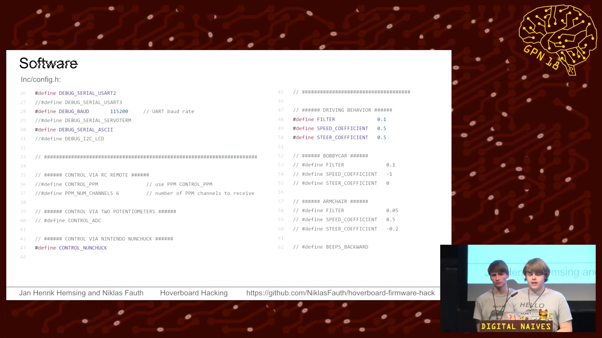
39 min 2018-05-11 Reverse engineering Hoverbard hardware for fun. In this talk you will learn how to flash your Hoverboard hardware with custom firmware to use it as an universal platform for all kinds of moving objects including armchairs, beverage crate, go karts... We begin with details and reverse engineering of original hardware and software. You will learn about our own software we developed for this hardware and how to flash it to your board. A good amount of time will be about hands-on tips on how to build you moving objects, both mechanical and electrical advice. There is also a workshop that you can join if you actually plan to build something.
This experiment will show how easy the Hoverboard controller can be manipulated. As shown in the video a TxD signal was given to all 4 inputs of the two motor controllers. In a robot project that would of course be a bit different. Then 2 UART (2x TxD) would drive the 4 wheels, per side a motor controller with 2 wheels. Config of the USART-Communication: 22500,N,9,1. That means 22500 Baud with 9 Data-Bits, no Parity, one Stop-Bit. Example of the data transfer: Data to send 6 Bytes (9 Bit) for STOP (Speed= 0000): 100h, 000h, 000h, 000h, 000h, 055h Data to send 6 Bytes for 10% FORWARD (Speed= +0150d): 100h, 000h, 096h, 000h, 096h, 055h Data to send 6 Bytes for 10% BACKWARD (Speed= -0150d): 100h, 0FFh, 06Ah, 0FFh, 06Ah, 055h Range for the variable "Speed" (decimal): -1600 ... 0 ... +1600 But I have seen different Motor-Controller with some Variation in the Speed-Range and Baud-Rate, so everyone have to figure out the Value for a specific Motor-Controller... - Uploader: AccuXperT - Uploader url: https://www.youtube.com/@accuxpert2277